What This Means for Your Project
The capability details below are intended to help engineering, quality, and sourcing teams evaluate execution reliability.
01
Lower redesign risk after pilot stage.
02
Faster issue isolation when performance deviates.
03
Better alignment between test data and release decisions.
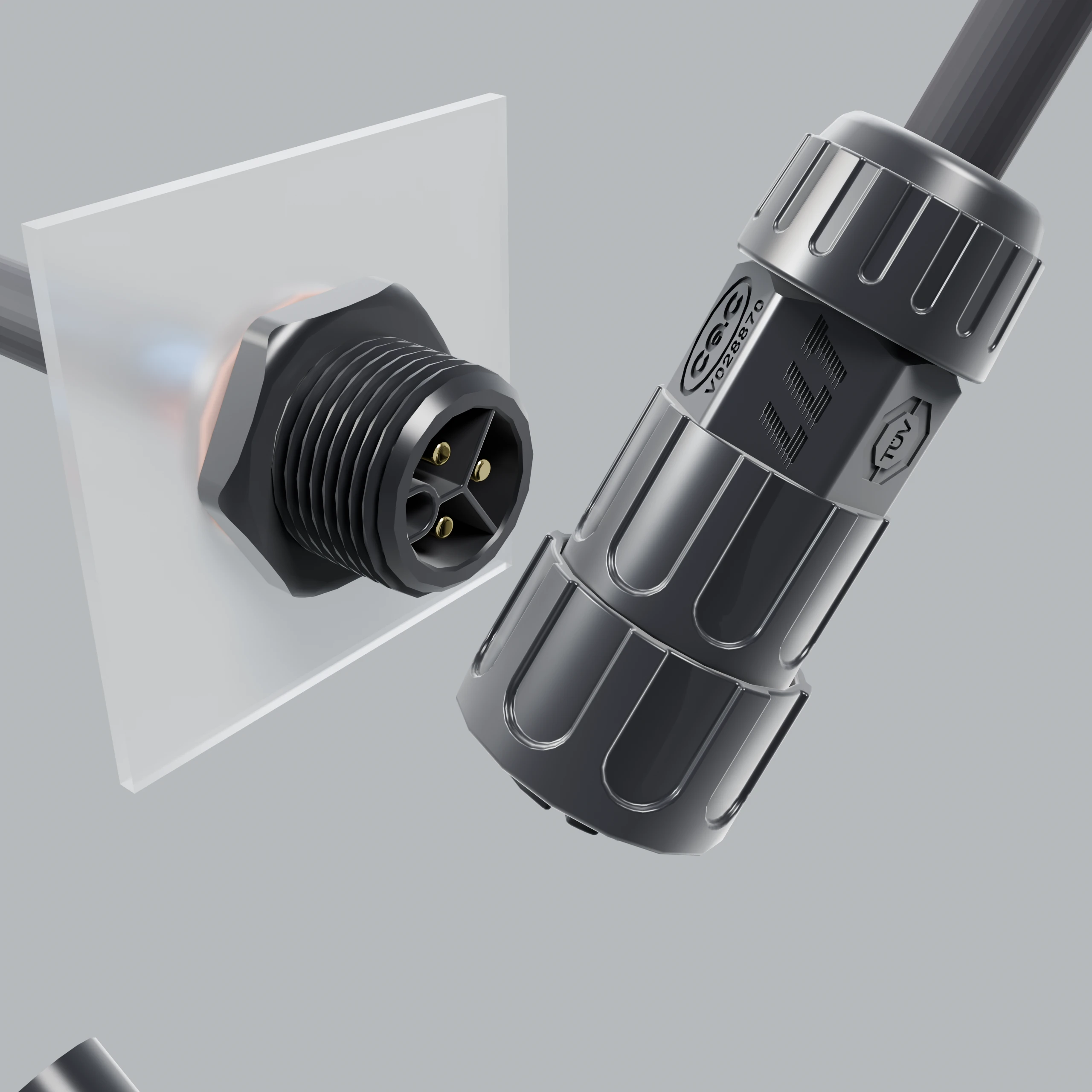
Engineering Support for Connector Adaptation and Project Development
R&D support covers interface requirement review, structure direction, prototyping, and manufacturability coordination.
Parameterization
Pin count, current, voltage, sealing, vibration, and installation pattern are defined as linked variables.
Design + Simulation
Mechanical and electrical checks focus on fit risk, heat behavior, and interface stability under expected loads.
Manufacturability Coupling
Design decisions are reviewed against molding, assembly, harness process, and final inspection feasibility.
Execution Flow
- Requirement model and boundary definition.
- Design alternatives and review loop.
- Prototype verification and failure capture.
- DFM confirmation before production release.
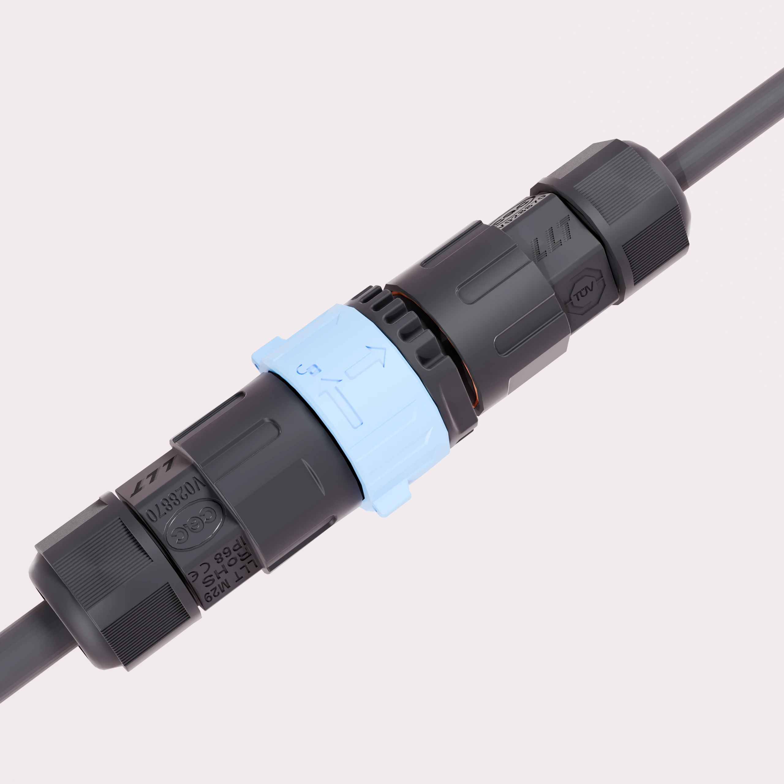
Critical Control Points
- Pin insertion force
- Mating-gap verification
- Molding completeness
- Lock depth
- O-ring compression state
- Terminal contact resistance
- Pressure / insulation / withstand checks
- Cut length
- Strip length
- Conductor condition
- Color / sequence consistency
- Crimp quality
- Solder quality
- Electrical validation
- Batch archive and release logic
- Abnormal isolation + CAPA + re-verification
What This Means for Your Project
- Lower redesign risk after pilot stage.
- Faster issue isolation when performance deviates.
- Better alignment between test data and release decisions.
Need engineering alignment before quoting?
Send your connector target, equipment background, or draft interface requirement for review.
Start Engineering Review